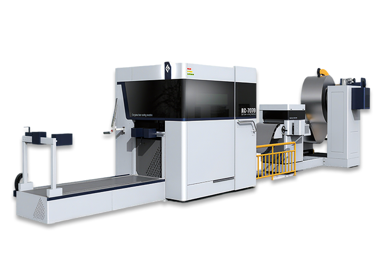
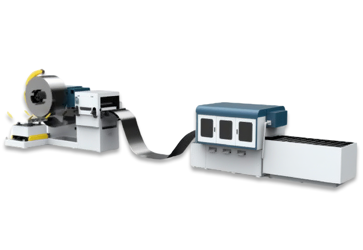
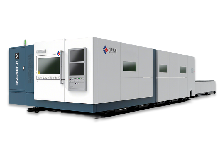
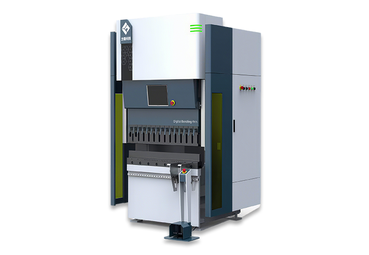
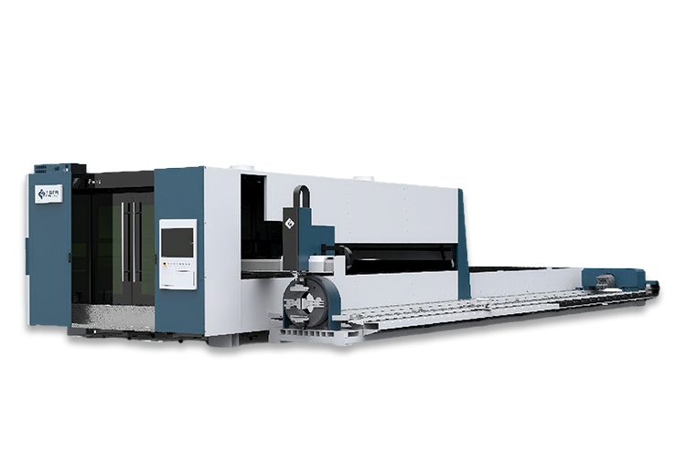
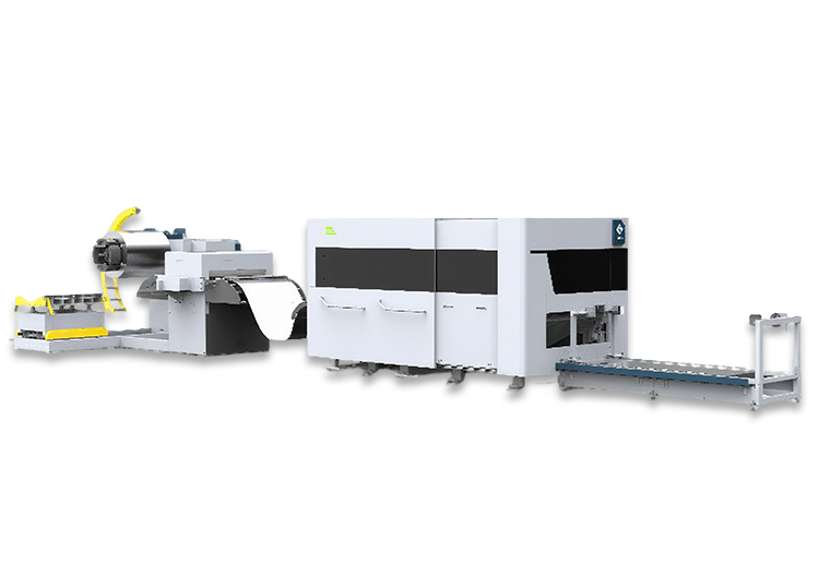
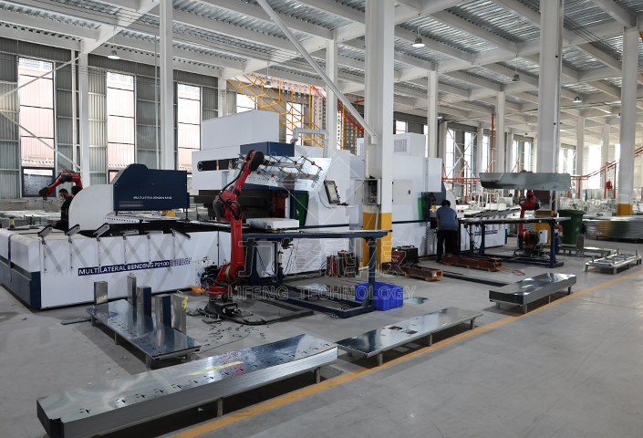
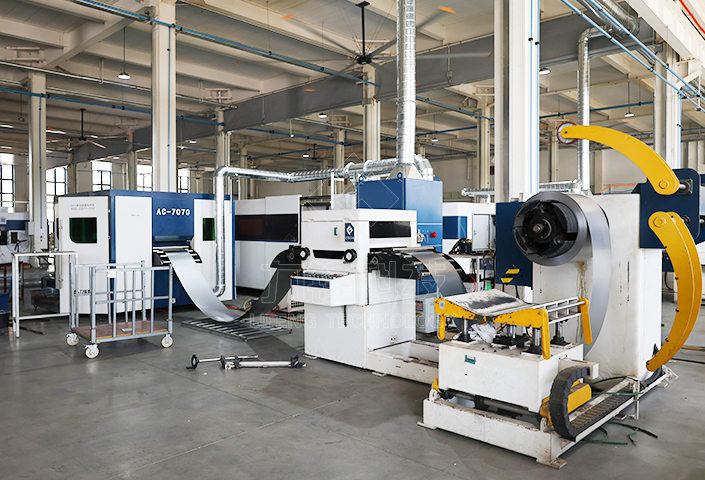
The phrase 0.3 to 6 mm sounds like a specification. In practice it is a warning: a twentyfold range in thickness means at least two handling philosophies inside one line, and the design work sits almost entirely in the gripper and the transfer stations rather than in the press brake.
The clip above shows the result in a customer plant, with robots loading blanks, bending, laser welding and stacking while nothing is carried by hand between stations. Below is what has to be decided before a line like that can be quoted.
At 0.3 to 0.8 mm a 1200 by 800 blank weighs under 7 kg and sags under its own weight when lifted at one point. Vacuum cups work, but they need enough of them, spread wide, and a generator that holds through an oily or slightly porous surface. Magnetic grippers are worse here: they concentrate force and leave marks on visible faces, which is fatal for cookware and parcel locker shells.
At 4 to 6 mm a part with the same footprint weighs 60 to 100 kg. Robot payload becomes the constraint, and so does inertia: accelerating a heavy blank into a locating pin at speed is how frames get damaged. Slower transfer, magnetic or mechanical grippers, and a fixture that absorbs impact are all part of the specification rather than options.
Cookware bodies are round and shallow, they nest in a stack and can be handled from the centre of gravity. Parcel locker shells are large thin-walled boxes that flex if gripped in the middle, so they need support at the corners and a transfer station that does not assume rigidity. Medical device parts are small and numerous, which shifts the problem to cycle time and part-present sensing rather than weight.
If every part needed its own mechanical setup, a mixed line would never pay back. Servo-controlled axes let one machine store and recall forming parameters for each part number, so a cookware body and a cabinet side can run on the same shift with a program change instead of a tooling rebuild. Adjustable transfer stations complete the picture: the distance between stations is set to suit the part, rather than the part being designed to suit the line.
A plant running a narrow set of part families at volume, with at least two shifts of demand to load the line. Cookware, medical enclosures, parcel lockers, electrical cabinets and furniture panels all fit the pattern; a job shop quoting one-off prototypes does not. The dividing line is repeatability, not sophistication.
Send us the thickness range, the heaviest part, and the monthly volume for each family. That is enough to say which stations earn their place and which would be capacity you buy and never use.
Customized Production Line Design, Full-Lifecycle Service Guarantee From Solution to Implementation, Empowering Enterprises to Reduce Costs, Boost Efficiency, and Achieve Zero Risks!
Thank you for your interest in Lifeng Technology. If you would like to know more
about our sheet metal
process and equipment,
contact us to find out what we can do for your next project!

 lydia@lftk.cn